SPICE simulations of openEEG-Hardware
The SPICE Simulations are done with the excellent freeware LTSPICE .Table of simulations:
1) modularEEG V1.x2) INA118
Comments, error reports, improvements are always welcome. (contact address)
modularEEG V1.x(updated 2006-02-04) |
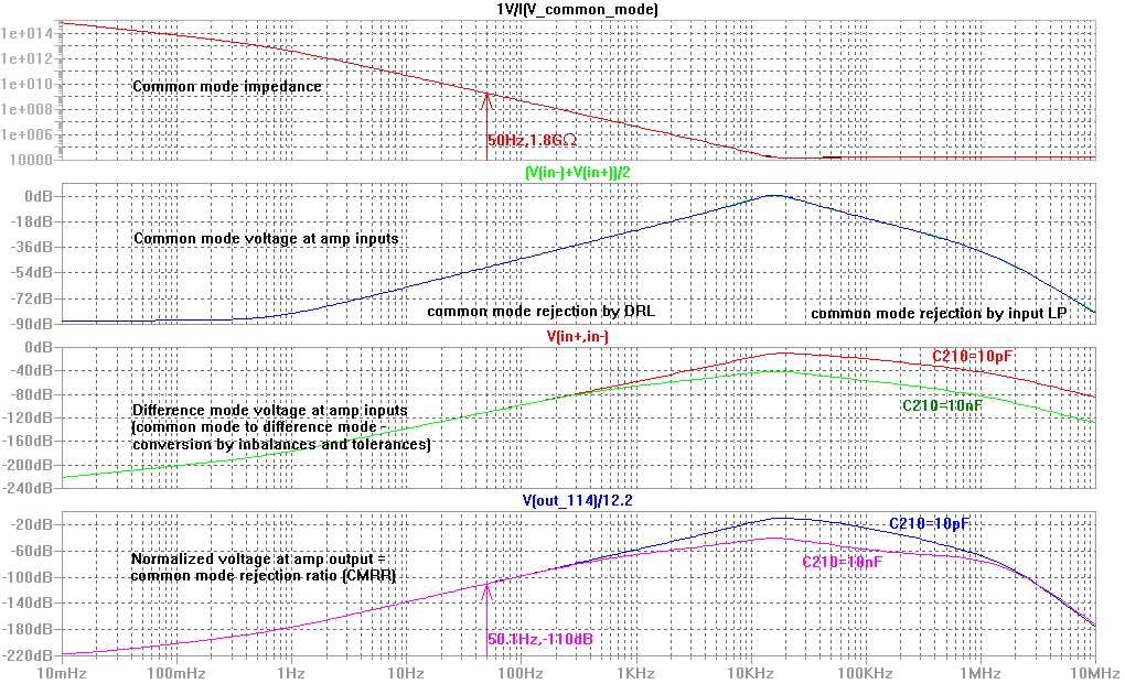 |
| The ohms over frequency graph for the common mode impedance is measured from DRL to both inputs. At 50Hz the common mode impedance is roughly 1.8 GigaOhms (Without DRL circuit it would be a few magnitudes lower) The graph also shows the CMRR over frequency. |
|
 |
|
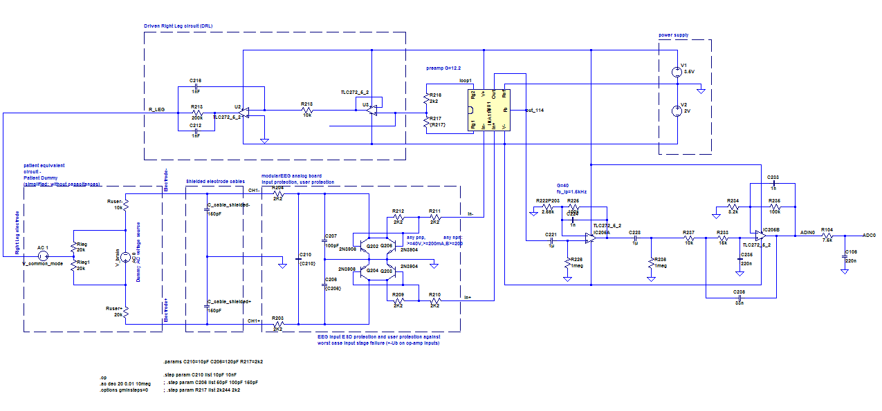
| LTSPICE schematics and libraries
used for the above graph: LTSPICE_modEEG_full_circuit_v1_1_0_CMRR_and_HF_bypass_01.zip |
|
INA118 with active highpass (Reference Integrator)(updated 2006-02-04) |
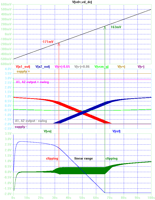 |
| The INA118
instrumentation amplifier internally uses a 3 opamp design with a superbeta bipolar input stage. From the datasheet: "... DESCRIPTION The INA118 is a low power, general purpose instrumentation amplifier offering excellent accuracy. Its versatile 3-op amp design and small size make it ideal for a wide range of applications. Current-feedback input circuitry provides wide bandwidth even at high gain (70kHz at G = 100). ..." The purpose of this simulation is to examine, if the often seen reference integrator (e.g. in INA118 datasheet FIGURE 6. AC-Coupled Instrumentation Amplifier) has substantial advantages over a simple output side passive C-R highpass in possible input and output voltage swing. Both swings determine the DC handling capability in EEG applications with DC coupled electrodes. If the maximum input or output swing for a given supply voltage, operating point and gain is exceeded, the amplifier is clipping the signal and works no more linear as required in EEG applications. |
|
 |
|
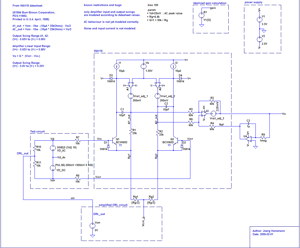
| LTSPICE schematics and libraries
used for the above graph and schematic: ina118-06.zip |
|